|
Under the Coach or in the Compartments: holding tanks and valves,
water pump (even if inside), water tank and external supply systems, spare tire, door step, gas
tank & sensor, exhaust system, the battery compartment, batteries and battery isolator, 110 volt docking cord, 110 volt generator and compartment and the access panels for the refrigerator,
hot water heater and forced hot air heater.
Click on the
 to
go to its Tip: to
go to its Tip: |
|
|
Holding Tank Gate Valves
|
|
|
Dragging or Replacing the Holding Tank Valves
|
|
|
Awkward Holding Tank Dump Valves
|
|
|
Electric Step not retracting and how it works
|
|
|
Electric Step Fuse
|
|
|
Electric Step Models
|
|
|
Electric Step Switch and Parts
|
|
|
Power Step Joints
|
|
|
How to Manually Retract the Step
|
|
|
Replacement Step
|
|
|
What is the best House Battery solution: 6 or 12 volt, 1 or 2 batteries?
|
|
|
Batteries -- Need wiring diagram.
|
|
|
Battery Isolator, Troubleshooting and Replacement.
|
|
|
Sliding Tray for Golf-Cart Batteries
|
|
|
External 110 Power Reverse Polarity
|
|
|
Pig Tail 50 AMP to 30 AMP
|
|
|
Voltage Booster for Low Campground 110 Voltage
|
|
|
Leveling Jacks - HWH Hydraulic
|
|
|
Leveling Jacks - A&E Electric
|
|
|
Hanging Wires
|
|
|
Gas Tank, Fuel Gauge Sensor & Fuel Pump
|
|
|
Gas Gage Accuracy (off Page link)
|
|
|
Fuel Tank Capacity
|
|
|
Gas Tank and Gas lines
|
|
|
Gas Tank Filler Neck
|
|
|
Exhaust System Wrap to cool things down
|
|
|
Exhaust System Replacement
|
|
|
Catalytic Converter
|
|
|
Generator Over-Voltage
|
|
|
Generator Fuel Line
|
|
|
Generac Generator
|
|
|
Honda Generator Won't Start
|
|
|
Honda Generator Removal for service
|
|
|
Water Heater Gas Burner & Replacement
|
|
|
Refrigerator Gas Burner
|
|
|
Keeping Gas Burners Clean and Bug free
|
|
|
Flat Tire? Use the Air Bag Compressor to fill it up. (off page link)
|
|
|
Flat Tire - How to change it
|
|
|
Spare Tire - Lowering and Raising
|
|
|
Fresh-Water Gauge
|
|
|
Water Pump Replacement 1
|
|
|
Water Pump Replacement 2
|
|
|
Recycling Grey Water
|
|
|
Running Gear Tips: Front & Rear Suspension, Wheels, Tires, Brakes etc. (off page link) |
-- Disclaimer --Information
on this Web Site is provided by members of the "Aero Cruiser Classics" Motor home Club. All
information on this site is contributed by the club members or outside sources and is believed to be reliable; however,
there is no warranty or guarantee that said information or advice is correct or free of defect. It is
offered on a best effort basis and is to be used at your own risk.
Tips:
Subject:
Holding Tank Gate Valves
Tip:
If you have a difficulty
opening and closing the gate valve, lubricate
the shaft with WD-40 oil and work it in-and-out.
If that doesnt solve the problem, replace the seals
but make sure you buy the correct manufacturer
and size seals from any RV store.
Update:
The valves are quite inexpensive. I recommend replacing the whole valve instead of just the seals.
It's actually faster and easer to replace the complete valve that to rebuild the
old one assuming you can find all the parts.
Keep on Cruisin' -- Tom Heald
Return
to the Tip List.
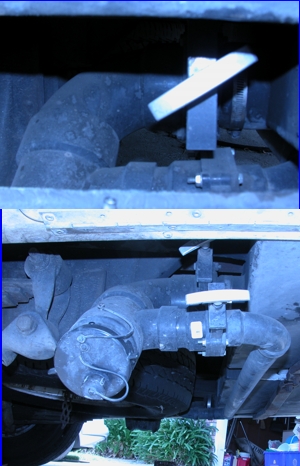
Subject:
Dragging or Replacing the Holding Tank Valves
Question:
The Holding Tank Valve is very low and I am afraid I may bump it when I am on
the road.
 Answer:
A number of Aero Cruiser owners have reworked their gray/black water
dump valve and managed to raise it a few inches. They differ from
coach to coach, so its a matter of looking at it and figuring out how
to save some space. I whacked mine once backing into a campsite on
the Blue Ridge Parkway. Answer:
A number of Aero Cruiser owners have reworked their gray/black water
dump valve and managed to raise it a few inches. They differ from
coach to coach, so its a matter of looking at it and figuring out how
to save some space. I whacked mine once backing into a campsite on
the Blue Ridge Parkway.  What a pain. I just
"Rube Goldberged" it together on the road with epoxy and didn't
raise it any at the time. Some years later I had to rebuild it and I managed to
raise it about an inch. What a pain. I just
"Rube Goldberged" it together on the road with epoxy and didn't
raise it any at the time. Some years later I had to rebuild it and I managed to
raise it about an inch.
The black ASB pipes, "Y" connector, elbow and ASB Cement are all standard plumbing items you can get at any
good hardware store. When I assembled mine I trimmed the connectors down as much
as I could to give me more ground clearance.
The holding tank valves and the adapters to the pipes and
fittings are also a standard part you
can pick up at any good RV Shop.
When I replaced the two valves in my rig, the new ones came with plated steel
bolts and nuts. The old ones had brass bolts and nuts which were, much to
my surprise, not corroded at all.  They were easy to remove, so I used the same brass bolts and nuts to reassemble
everything.
They were easy to remove, so I used the same brass bolts and nuts to reassemble
everything.
Keep on Cruisin' -- Tom Heald
Return to the Tip List.
Subject:
Awkward Holding Tank Dump Valves
Tip:
Some coaches have
their dump valves installed in such a way that
requires acrobatics to operate. Bruce suggested
installation of solenoid operated valves available
at RV stores for easy remote operation.
Return
to the Tip List.
Subject:
Electric Step not retracting and how it works
Tip 1:
The first thing to try is the "Step" switch on the instrument panel to the left of the
searing wheel. It controls whether the
(1) step opens and closes every time the side door is opened and closed or
(2) weather the step stays down until the rig is started with the side door closed.
Start your rig, close the side door and see if changing the switch makes any difference.
Keep on Cruisin', Tom Heald
Tip 2:
Don't know if you step is up? Ken installed a NAPA
door jamb switch (DJ6300) on the rear of the coach
step bracket and a VDO green warning light (600 845)
on the dash. If the step does not retract and open the
switch, then the green light is on when he starts the
Engine.
#215 Stahl Update:
Sometimes the coach step would not retract and
sometimes, it would not extend. The door jamb switch
which controls the step, located on the right side of the
door jamb, near the bottom was in contact at the back
of the switch on the frame. With the switch making
contact, the step control thought the door was still
open. So, Ken installed some insulation around the
back of the switch. So far, the step is working.
#215 Stahl
Return to the Tip List.
Subject:
Electric Step Fuse
Tip:
The electric step is controlled by a 5 amp fuse. It the fuse
burns, replace with the same rating. Do not install higher
rated fuse.
Return
to the Tip List.
Subject:
Electric Step Models
Tip:
At the last rally we discovered the Aero Cruisers have
three different models of Electric Steps. They all have
different mechanical parts and control boxes. Quick
reference is to check color of the control box.
white, blue, or orange. Big help when looking for replacement
Parts!
#102 Kinnison
Return to the Tip List.
Subject: Electric Step Switch and Parts
Question:
Well, I've tried 2 supply stores looking for a replacement switch for my
electric step. Trouble is knowing what the heck to ask
for. I've not been successful in trying, even asking for info on the
"kwickee" step. Maybe you know how to get to the right place??? --Tom
Answer:
This may be your switch, as I have this kind: http://www.kwikee.com/Images/905307.jpg
Here
are all their switches: http://www.kwikee.com/Aparts_steps.html#switch
Note
that that is at www.kwickee.com. You can
click on each switch to see the picture. Beware that some of those switches are
closed unless activated (by the matching magnet) and others are open until
activated. You must get the right one. Best is to report to them the color of
the control box and that it is a 1989-or-so vintage, so you get the right
one. Probably won't cost much even from Kwickee.
--Frank
Update:
Just wanted to let you know that my switch is different. I found the switch
I need after much
sweating over the computer. It's a Honeywell micro switch which is
no longer manufactured and no replacement is made. All distributors
are out of them except "Electrol" which has 48 of 'em on their shelf
and they are $75.00 each. Ain't that a good 'un?? The supplier is "www.electrolsupply.com", and the phone# is (800)663-6576.
Tom Even
Return
to the Tip List.
Subject:
Power Step Joints
Tip:
Make sure you lubricate the Power Step
joints routinely to keep it moving free.
Return
to the Tip List.
Subject:
How to Manually Retract the Step
Tip:
The first thing to do is to check for a blown fuse and then try the switch in different
positions as explained in the tip above. In the short
run to get the steps back in, you can remove the cotter pin then knock out the
pin that connects the gear box to the lever on the step unit and tie the step
up. From there you would need to troubleshoot to determine if the problem is
electrical or mechanical. When my steps did this, I found the motor to be the
problem. I took it apart, polished the armature and cleaned the gaps between the
copper bars. When I put it back together I had to reset the armature end play
using the allen head set screw.
Good Luck!!!
Walter
Return
to the Tip List.
Subject:
Replacement Step
Tip:
If you have the original that came with the A-C and it stoped working, it may have finally died. The
ones produced the late 80s - early 90s were a little anemic. Kwikee Step in
Oregon has a rebuild kit with a better, more robust motor and new
electronics. But for about $20 more, you can get a new unit out of Camping
World.
-=Dale=-
Return
to the Tip List.
Subject:
What is the best House Battery solution: 6 or 12 volt, 1 or 2 batteries?
Question:
A friend of mine said to replace my 2 bad house batteries with two 6 volt rather
then two 12 volt. Said the amp hours are longer. Anyone else done this?
Answer:
Using two 6 volt Deep-Cycle batteries hooked up in series is a good solution; but it
tends to be a bit expensive. There is a common misconception that two 6-volt 200 amp-hour
batteries used in series will double the amp-hours available. This is not true. It will
double the available power (watts) but not the amps.
Remember back in your high-school science
class the formula W = V*A? That's Watts = Volts * Amps. One 6-volt battery times 200
amp-hour = 1200 watt-hours, times 2 batteries = 2400 watt-hours. One 12-volt, 200 amp-hour
battery = 2400 watt-hours. Each setup will deliver the same amp-hours and wattage given the
stated ratings.
Using two 12 volt Deep-Cycle batteries hooked up in parallel will also work as long as the batteries
remain a matched pair. In this case you will get the total amp-hours of both batteries. For example:
12 volts times 130 amp-hours = 1560 times 2 = 3120 watt-hours. The problem is that
as they grow older and one battery becomes slightly weaker, it will draw down the other battery even with no external load from the camper. This
constant load will cause one or both to fail much faster than they might under a normal load. A
standard battery
isolator won't solve the problem because both batteries share the same load.
You could design one, but I don't think it is worth the effort.
So, contrary to the myth, two 12 volt, 130 amp-hour batteries will deliver more power than two 6 volt, 200
amp-hour batteries. A "good" salesman may tell you that's a load
of bologna; however, any
"honest" salesman will
tell you it's true.
My preference is to install the largest 12 volt Deep-Cycle battery I can
find. One with the most amp-hours,
that will fit in the available space. It will cost less than either of the other solutions,
deliver about the same power and almost certainly last longer than two 12 volt
batteries in parallel; probably 2 to 3 times longer.
Number and Type of
Deep-Cycle Batteries Used |
Amp Hours
at 12 Volts |
Watt Hours |
Approximate Cost |
| 2 - 6 volt 200 amp hour Batteries |
200 |
2400 |
$200 |
| 2 - 12 volt 130 amp hour Batteries |
260 |
3120 |
$150 |
| 1 - 12 volt 210 amp hour Battery |
210 |
2520 |
$90 |
My personal experience: When I purchased my 1990 Aero Cruiser in
1996 it had two 12 volt coach batteries, both dead. When I removed,
charged and tested them, one was good and one bad. I replace the bad one
and one year later they were both bad.
Almost the whole time they were
sitting in the driveway with the charger on, which was a mistake. I unplug
the coach and put it on a timer so it only run the charger for an hour a day and
then I replaced the house batteries with two identical 130 amp-hours (if memory
serves) 12 volt Deep-Cycle batteries.
They lasted 3 years which is the low end of a batteries 3 to 5 year life expectancy.
Not happy, I checked around for two 6 volt Deep-Cycle batteries. I found a
pair of 200 amp-hour batteries for about $100 each if I remember
correctly. While talking to various sales people I received both stories
on the amp-hours, so I did the math myself and went out and bought one large 12 volt Deep-Cycle
210 amp-hour battery for under $90 that takes up the same space as the 2 smaller
12 volters. That was back in 2003 and it is still working in 2011.
So what is the difference between a "Good" salesman and an "Honest"
one? Well, it's all in the eyes of the beholder! After all, the "Good"
salesman is always beholding to the sales manager!

Keep on Cruisin', Tom Heald
Update:
In my 1990 23' rear bath model with the slide out battery compartment to the
right of the main entrance door, I use a 12 Volt Group 24 (11" Length x 6
3/4" width x 9 1/2" height) for the truck battery and a 12V Group 29M
(13" Length x 6 3/4" width x 9 1/2" height) for the coach battery
both running lengthwise with a 13" 4x4 and some thin shims to fill the
4" gap between them so they won't move around.
As an alternative there is room for 2 Group 24M batteries length wise next to
the single Group 24 truck battery taking up all of the remaining room. They can
be 2 - 6 volt batteries in series or 2 - 12 volt batteries in parallel.
The pros & cons of each of the three options are explained above.
Keep on Cruisin', Tom Heald
Return to the Tip List.
Subject: Batteries -- Need wiring diagram.
Question: Hi, I'm in need of
a wiring diagram for my 23' Cruiser. Some how before I got it the cables to the
batteries were replaced and I don't think that they put back were in the right
order. I have to use BATT Boost every time to start the engine, or generator.
Thanks for any help you can give me. Tim Meyer
Answer: It's pretty straight forward.
Each of the batteries go to a CB (a round self resetting circuit breaker) then the
Battery isolator and the two large relays in the Coach Electrical Box (the
Ignition and Crossover relays) found in one of three places:
* the Front Compartment under the Hood or
* inside the cabinet under the Refrigerator or
* under the interior front Step.
The first thing to check is if all the batteries are charging correctly.
If yes, then you can assume that everything from the
Battery isolator to the batteries is ok and look on the other half of the circuit
for the problem. You can trace
all of it out with a meter by following the wires under the coach and look for a
loose or dirty connection along the way. Go here for the wiring
diagram of the Coach and Truck Batteries.
Keep on Cruisin' -- Tom Heald
Return
to the Tip List.
Subject:
Battery Isolator, Troubleshooting and Replacement.
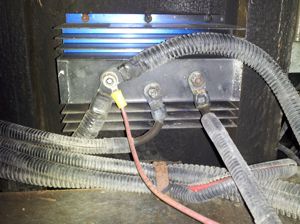 Tip:
My batteries were dead and I had an appointment to get it serviced. Bummer! To troubleshoot the problem I grabbed my voltage meter
and crawled under my rig beneath the passenger compartment. Tip:
My batteries were dead and I had an appointment to get it serviced. Bummer! To troubleshoot the problem I grabbed my voltage meter
and crawled under my rig beneath the passenger compartment.
With the engine running and no AC power to the coach, I checked the voltage and had 14+ volts coming into the
center post of the
Battery Isolator; however, the battery side showed low voltages -- 10 or so volts indicating
a dead battery. I charged the batteries and they held there charge.
I drove it around and then checked again. Everything worked ok and did no
give me any more problems and when I checked it later with the engine running, I had 14+ volts on the
center post coming from the alternator and 14- volts
on the
battery sides. Just as it should be when charging.
Note: The red wire seen in the pictures
is an add-on. It goes to a post I added under the front hood so I
can hook my generator's battery charger up to the house battery
there. The Battery Isolator consists of two diodes inside a sealed unit.
Its job is to allow current to flow from the alternator to each battery while stopping
any
flow between the House Battery and the Truck Battery circuits. It is a solid-state
device. There
is nothing to stick and there is no ground to the Isolator except at the batteries. My conclusion. There must have a been a bad connection
inside the
Battery Isolator which is a solid-state unit sealed with epoxy. Just to be on the safe
side, I ordered a new unit -- NOCO
IGD140HP Grey 140 Amp High-Performance Battery Isolator for $35.34 on Amazon in
2012. 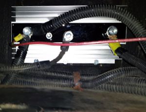 I had no more problems over the next
several months. It was some time before I decided to install the new Battery Isolator. The new
unit has an extra post that is not used on the Aero Cruiser it is for some
alternators found on more resent trucks. The unit is larger than the old one but
fit into the same location. The only problem, the connecting posts were
larger so I had to drill out the connectors to fit. I should have clamped
the connector to a backing board when drilling so the drill wouldn't catch and twist
off the connector. I didn't and had to replace one connector. I believe
the larger posts are required by law on newer units. The
older 120 amp Sure Power 1202 Battery Isolator I replaced had
smaller connecting posts. It is still available online though
it is a bit more expensive and is prone to this problem. I had no more problems over the next
several months. It was some time before I decided to install the new Battery Isolator. The new
unit has an extra post that is not used on the Aero Cruiser it is for some
alternators found on more resent trucks. The unit is larger than the old one but
fit into the same location. The only problem, the connecting posts were
larger so I had to drill out the connectors to fit. I should have clamped
the connector to a backing board when drilling so the drill wouldn't catch and twist
off the connector. I didn't and had to replace one connector. I believe
the larger posts are required by law on newer units. The
older 120 amp Sure Power 1202 Battery Isolator I replaced had
smaller connecting posts. It is still available online though
it is a bit more expensive and is prone to this problem.
Keep on cruisin', Tom Heald
Return
to the Tip List.
Subject:
Sliding Tray for Golf-Cart Batteries
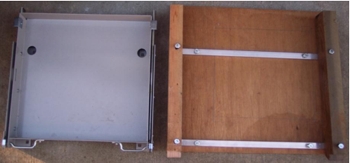 Tip:
My Cruiser was modified by the prior owner. He moved the 12v engine battery
elsewhere and put two 6v golf-cart batteries in the original compartment just
in front of the entry door, under the third chair, to supply coach power. He
made a non-sliding box to hold those two (taller) batteries. It was a pain to
get water into the batteries. I found on eBay a sliding tray made by Kwikee:
product #905700010, which is shown in the first picture, along with a pair of
aluminum channel supports, a thin floor, and two strong side supports. Tip:
My Cruiser was modified by the prior owner. He moved the 12v engine battery
elsewhere and put two 6v golf-cart batteries in the original compartment just
in front of the entry door, under the third chair, to supply coach power. He
made a non-sliding box to hold those two (taller) batteries. It was a pain to
get water into the batteries. I found on eBay a sliding tray made by Kwikee:
product #905700010, which is shown in the first picture, along with a pair of
aluminum channel supports, a thin floor, and two strong side supports.
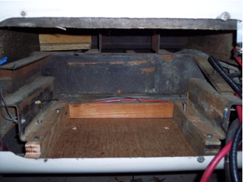
The
space I had to work with is shown in the next photo to the right, with the support box installed.
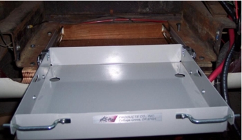 Then with the tray
extended: I had to trim the fiberglass below about 1/8th inch to get enough
depth for these tall batteries: Then with the tray
extended: I had to trim the fiberglass below about 1/8th inch to get enough
depth for these tall batteries:
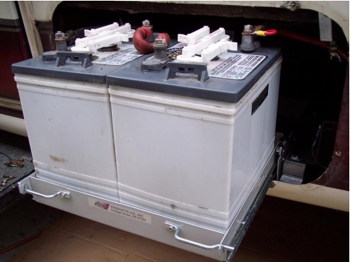 And
finally, box painted black, permanently installed, and loaded with the batteries: And
finally, box painted black, permanently installed, and loaded with the batteries:
Not a bad solution. Now I will be more faithful at adding water!
P.S. Because the golf-cart batteries are so tall, I had to trim the lower
fiberglass about 1/8 inch to allow the tray to come out. That also means I have
to remove the door and its frame (four screws) to slide the batteries out, as
shown. This tray would also work for the original (shorter, 12v) batteries, but
the floor would not have to be so deep and there might be enough room for the
tray to come out without having to remove the door. Someone else will have to
try that.
--Frank DeRemer Update:
The original plastic, sliding battery tray in my 1990 Aero Cruiser measures
14" deep, 18" wide and provides 10 inches of clearance for standard
sized batteries. Franks tray is 13 3/4" wide x 13" deep and
can accommodate batteries that are 11" tall.
Keep on Cruisin', Tom Heald
Return
to the Tip List.
Subject:
External 110 Power Reverse Polarity
Tip:
Although shock from the improperly wired
receptacle itself is not likely, it can be
dangerous for an RV connected to a power
source with reverse polarity. If the power source
is not correctly wired, your RV itself can become
hot, which means you could become a
conductor if you were to touch your coach while
walking around the outside. Obviously this could
cause serious injury or even death under certain
circumstances.
Another risk is that the safety mechanism on
an electrical device connected to a reverse
polarity source of power may not kick in, which
could cause serious injury. For example, a
power tool may start automatically as soon as
its plugged into the improperly wired receptacle
or it may not shut off when you try turning it off.
Before you hook up to any unknown power
source, you should use a circuit tester to check
for correct wiring. Plug the tester into all the
receptacles both top and bottom for an
accurate reading. You should always test the
outlet before hooking up, but if youve already
plugged in, unplug your RV and dont use the
outlet until its repaired. Make sure to report the
problem to the campground owner at once.
Good Sam
Return
to the Tip List.
Subject:
Pig Tail 50 AMP to 30 AMP
Tip:
When traveling in
summer time, you may come to a park with inadequate
30 AMP service if everyone has their air
conditioning on. It is suggested you get a 50 to 30
AMP pigtail so you can actually use the parks 50-
amp circuit, which is less likely to be overloaded.
dragi
Return
to the Tip List.
Subject:
Voltage Booster for Low Campground 110 Voltage
Answer:
Elizabeth writes: I met Frank Izbinski who lives in
my town and thought he had an interesting
product, Voltage Booster for RVs. Toll Free 888-
624-3347. He will be selling at his booth at the
Quartzsite swap meet. Since I dont know anything
about this stuff I thought I would pass the
information along for you guys to check out.
www.voltagebooster.com
#139 Haynes
Return
to the Tip List.
Subject:
Leveling Jacks - HWH Hydraulic
Tip 1:
Ken had a spring break on one of the HWH Hydraulic
Leveling Kickdown Jacks, 110 Series.
He went to www.hwhcorp.com, then technical
information, repair parts manual, jacks, kick-down and
finally AP7129. The replacement is R6824 spring kit
1.5 x 10. The kit contains two springs and retaining
pin. The cost was $12.21, plus shipping of $4.90.
Installation is relatively easy. The replacement springs
are 1' shorter, so requires some muscle.
In the retracted position, pull pin and remove springs.
First, need to twist the spring to break the paint. Install
the two new springs and pin. Using some nylon line and
a loggers hitch knot with one end to the spring and the
other to the coach frame, he pulled the spring into
place and slipped the spring end into the hole on the
foot. Slick!
#215 Stahl
Tip 2:
Rick bought spring replacements from HWH
(#R6824 Spring Kit 1.5 X 10) for his leveling jacks. Cost
$12.00 per pair plus shipping.
Ken Stahl wrote in a tech tip back in 2003 (Report
#034, Nov 2003, page 14), how to change the springs.
His technique for stretching the springs to snap onto the
jacks foot required the knowledge of tying a lumbermans
knot or something like that. Anytime Rick hears
of a complicated knot he just adds three or four more
granny knots!
The job turned out very easy (even for him!). He got
a ratchet tie down strap, tied one end around a stationary
part of ole Aero then made a 6 loop of nylon line
hooked to the spring and the hook of the ratchet tie
down. After tightening the ratchet to stretch the spring
opposite the slot on the jacks foot, he twisted the open
end of the spring into the slot then took a knife and cut
the nylon loop with the springs snapping into place.
Make another nylon loop and repeat. Worked
slicker than snot.
#101 Krafft
Return
to the Tip List.
Subject:
Leveling Jacks - A&E Electric
Tip:
For those needing replacements for A&E electric levelers,
check the following link:
http://www.powerpluslevelers.com/prodctr/aejack/aejack.html
or call Power Plus at 800-934-6585. They have a direct
replacement for Mark II and V leveling jacks.

#375 DeRemer
Return
to the Tip List.
Subject:
Hanging Wires
Tip:
Everyone should get under their coach periodically and
check for any hanging wires or wire bundles. The one
with a significant risk is the cable connecting the battery
to the generator. It may be laying over the drive shaft and
rubbing against it. Look for the broken wire ties and
replace them if necessary. Make sure you use black
wire ties. They last longer than the white ones.
#462 Wachtell
Return
to the Tip List.
Subject: Gas Tank, Fuel Gauge Sensor & Fuel Pump
Question:
Do you know if any of the Vironex Chassis had fuel-injected engines or if the LGS Chassis
had carbureted engines? It appears from the fuel tank shop drawings that fuel-injected
engines were first installed when the LGS Chassis was introduced. The shop drawing
dated 1-24-89 indicates a change for the LGS Chassis. J. D. Whistler, '88-1989 23' Rear Bath
Answer:
I don't know but I believe the manufacture used whatever was in stock when it built the
chassis. So when they switched from Vironex to LGS Chassis any carbureted
engines on hand were probably used; however, the majority of the LGS Chassis
have the fuel-injected
engines.
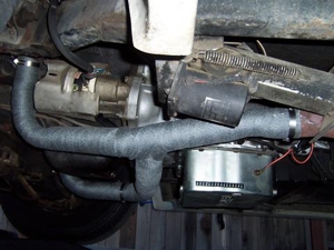
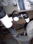
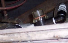
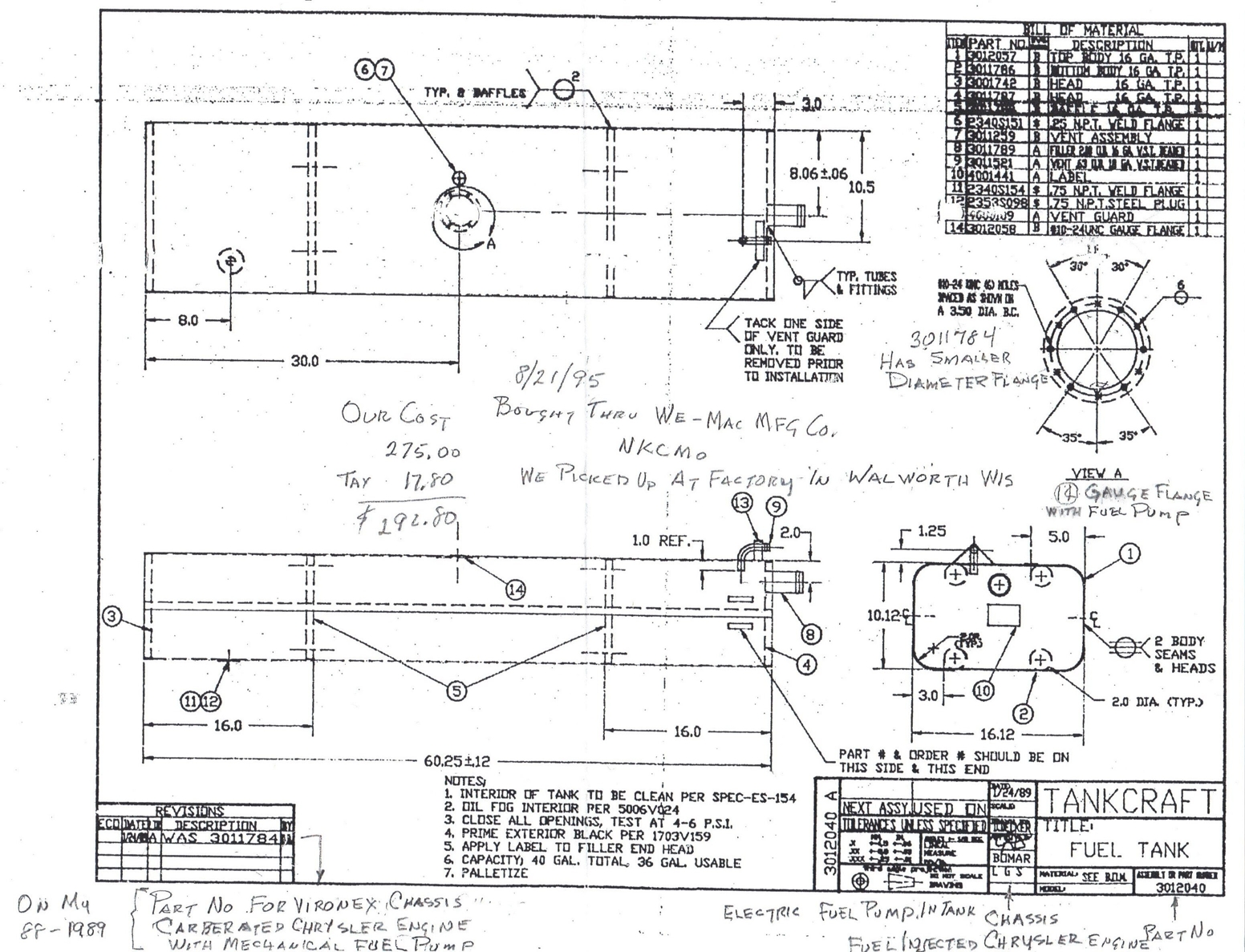
Tip: I finally found my
stuff on the gasoline tank. The tank is manufactured by the Tankcraft Corp. The
tank came ready to install.
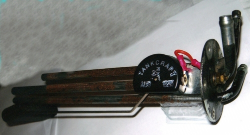
1) Tank Part No. 3011784 came with a fuel gauge sensor for the carbureted
360 engine which has a mechanical fuel pump. In the picture above
note that the short fuel line is for the generator, the two longer ones are for the
feed to the fuel pump and the return line. They are long enough to reach
35 gallons of fuel, leaving 5 gallons to prevent any sediment from being sucked up.
2) Tank Part No. 3012040 comes with the fuel gauge sensor and electric fuel
pump mounted on it for the 360 fuel-injected engine.
Tankcraft made me a tank Part No. 3011784 in 1994. It had developed a
multitude of pin holes. I had to go through a local tank supplier to buy it. It
cost $275.00 plus $17.80 tax in 1995. I picked it up at the factory. I still have the
old tank and fuel gauge sensor. The sensor is stamped with "Tankcraft 90
OHM - 1985," but no part number.
Click here to display a high resolution
drawing of the Fuel Tank suitable for printing.
Use print preview: "Landscape" mode, "Shrink To
Fit" to print.
The tank shop drawing I have shows the tank part number on the label applied to
the right side of the tank at the fuel filling end of the tank. Another
label is applied on the fuel filling end. This is where I found the part number
on my tank but was listed as the model number. I think if you call Bevan
Kreinbring, he could tell you how to get a fuel gauge sensor at:
Tankcraft Corporation
N2900 Foundry Road
Darien, WI 53114
Telephone: +1 262 882 2500 Fax: +1 262 882 2501
http://www.tankcraftcorp.com/contact/
If I could use a computer like Tom Heald, I would send you a copy of the tank
shop drawing. Tom sure does an outstanding job as Webmaster. I'm lucky to be
able to send an E-mail.
J. D. Whistler, '88-1989 23' Rear Bath
J.D. Thanks for the drawing, picture etc. Tom
Return
to the Tip List.
Subject:
Fuel Tank Capacity
Tip:
If you would like to know what the capacity
of your gas tank is, measure and multiply
width by height by length (in inches) and divide by
230. That will give you total gallons. Subtract 10%
for expansion and that will give you net capacity.
Since the gas gage sensor is mounted in the middle
of the tank, the gas gage may show more or less
depending on how level your coach is at a given
moment.
Update:
You may have heard an ugly rumor how Dragi ran out of
gas on the way to Quartzsite. For the record, that is not
true. In reality, I was running an experiment to see how
much gas our tanks really hold so I could share that
information with the rest of our members.
The label on the tank shows capacity as 40 gallons.
That may be if you stand it on end but in its present
position, it holds 32 gallons. On the way back, when
the gage read 1/4 tank, I filled it up again and it took 28
gallons. In reality, I had only 1/8th of the tank left. That
tells me dont let it get below 1/4 tank.
My sincere thanks to Wright Benson and Trish for
taking me to the gas station so I can complete this
valuable research and report the results to you.
#212 Petrovich
Return
to the Tip List.
Subject:
Gas Tank and Gas lines
Tip:
1990 (1988 Chassis) Gas Tank
The fuel pump (mechanical) on my
Dodge engine just wasn't working right. I
changed it out, added new fuel
filters...it was still hard to start, turning
over forever before starting.
In some cases I even started "priming the carb"
go get it going. My
driveway is on a slant, the gas lines would go dry. Why?
Finally, I
removed the gas tank. Two steel straps. Found that at the the top
of the tank
are a set of fittings, connected with rubber hose. The rubber hose
gas line
had cracked, thus the fuel pump was sucking air . I replaced the
rubber
lines.
I also cut an access hole in the floor: now I can get at the top
of the tank
where the connections are. Oh... the car no longer smells like
gas all the time
either!
George Baldwin
Return to the Tip List.
Subject:
Gas Tank Filler Neck
Tip:
If you need to replace yours,
go to a Toyota dealer and make sure that there is an
insert for the small gas pump nozzles. This is one of the
items checked during emission test.
Return
to the Tip List.
Subject:
Exhaust System Wrap to cool things down
Tip:
On our 1989 Aero Cruiser I had installed a deeper transmission pan that had vents to draw air through the pan to keep oil cooler. Ran into the problem in that the right side exhaust cuts across to the left directly in front of were the cooling vents of the oil pan is located.
Went to local NAPA and purchased 15 feet of 1" exhaust wrap to cover this area.
To get the Aero Cruiser ready to work under, I first went and purchased a couple 12,000# drive up ramps to give me room to work. Chalked rear wheels and used jack stands for safety. This made it much easier to work under the coach.
I read the directions enclosed in packet and wrapped the section in front of the oil pan. 15 feet doesn't go far but did cover the cross over section. To secure the wrap I used two 2.5" stainless steel worm drive band clamps.
I told a co-worker what I did the next day and he said he had an extra 50 foot roll of 2" wrap he had gotten from Summit racing supply. I bought it from him.
That evening, with the Aero Cruiser still up on the ramps, I got under with the new roll, utility knife and two more band clamps.
Starting on the LEFT side, I unrolled about 15 feet of the roll (without cutting) and begin wrapping it around the exhaust until I had wrapped it loosely about 40 times.
Taking the end up to the bottom of the manifold, I used a band clamp to secure. Then the process of moving the wrap into position around the exhaust pipe. I used a 1" (half the width of the wrap) overlap since I had 50 feet and pulled tight as I went.
When I figured I had enough to get just past the point where the right side joins the left, I cut the wrap and finished the left side. Using a band clamp to hold temporarily.
Then to the right side following the same process. I went down to the cross over area and stopped (where I had placed the 1" x 15' section) instead of trying to do the whole length at one time. It cost me one more clamp but made it easier to deal with a shorter length of wrapping material.
Then from there to the joint area and then back to the catalytic converter, overlapping the wrap from the left side.
Project took about two hours. Results were a quieter cabin, cooler temperatures in engine compartment, starter doesn't get as hot, vented transmission pan gets cooler air.
Price of whole project under $100. Difficulty level 3 out of 10.
Rod Michaelson, '89 rear bath
Return
to the Tip List.
Subject:
Exhaust System Replacement Tip: If you
ever replace your exhaust system you have a chance to correct some engineering
problems with the original system. The Aero Cruiser's exhaust system is
too close to the starter motor and the transmission. As a result both suffer
heat-transfer problems because of it. Make sure the company who replaces
the system is aware of these problems.
- The pipes coming of the header needs to be a little bit longer and angled outward
to give more air
space between the starter motor and the exhaust pipe. See Tip "Starter
Overheating" for more information.
- The crossover pipe should be father away from the transmission without going
over the oil pan area.
- Leave enough room around the transmission so you can install a 4 inch deep oil pan
pan onto the transmission. See the picture on Tip on "Exhaust System Wrap to cool things down".
Even if you don't install a deeper oil pan, you want to leave the room for
cooling. It may save you a burnt out transmission.
There is plenty of room for all of this, and it should not add to the cost at
all.
Keep on Cruisin', Tom Heald
Return
to the Tip List.
Subject:
Catalytic Converter
Tip:
If you need to install or replace
your existing catalytic converter, it was suggested that
you are better off going to a reputable muffler shop
rather than going to the Chrysler dealer.
Kinnison
Return
to the Tip List.
Subject:
Generator Over-Voltage
Question:
My Generac 5200 is putting out 147 volts. Anyone know if that means a simple
replacement of an output voltage regulator? Thanks, --Frank
Answers: From several
members.
Warning: An over voltage situation can blow the circuit boards in the Refrigerator,
Air Conditioning, Microwave and anything else electronic even when these units are turned off.
 So I would check the voltage with a load,
then disconnect the load and check it again (it may read higher). Just to be
on the safe side, I would adjust it without a load first (to make sure your are
adjusting it down) and then fine tune it with the load attached. If you
need a "Safe" load to adjust it, use a 100 watt bulb
So I would check the voltage with a load,
then disconnect the load and check it again (it may read higher). Just to be
on the safe side, I would adjust it without a load first (to make sure your are
adjusting it down) and then fine tune it with the load attached. If you
need a "Safe" load to adjust it, use a 100 watt bulb
 or something you don't mind replacing.
Never tune the generator's engine, adjust the carburetor or "GOOSE IT" with
the coach load attached. Doing this can lead a grown man to cry,
become very agitated  and cost a lot of bucks!
Keep on Cruisin' Tom Heald
The Generac output voltage regulator IS adjustable. there is a screw potentiometer on the regulator body. It is located inside the generator
fuse panel and is easy to get to. That being said, there are quite a few 120V and 12V lines in there that can be grounded by a misplaced
screwdriver. 
I was able to adjust mine a few times before it had to
be replaced. There are several part numbers that superseded my old
one.
Note: The regulator is mounted on the back
wall of the box that is revealed when you removed the screws holding the two
breakers. It has 4 bolts holding it to the wall. The adjuster is on the front
face.
Rick
Warning: Wrap your screw driver with 3 rounds of electrical tape. UL approved tape is
50V dielectric un-stretched. Also check the governor's operation. If it is
allowing the genny to over speed, you will get too high a
voltage.
-=Dale=-
Return
to the Tip List.
Subject:
Generator Fuel Line
Tip:
Inspect the fuel line going
to the carburetor. A number of them have been
found with severe cracking and gas leaking onto a
potentially hot surface. These hoses wear with
time and should be replaced.
Return
to the Tip List.
Subject: Generac Generator
Tip 1:
If your Generac generator fails, take a look
at the relay which seldom fails but it could. More likely
culprit may be the oil pressure switch or just low oil.
Tip 2: Here is a copy of the Diagnostic
& Repair Manual for the Generac Generator courtesy of George
Baldwin. and some pointers from Frank:
Generac Diagnostic Manual
Generac Technical Information Manual
Return
to the Tip List.
Subject:
Honda Generator Won't Start
Question:
I few weeks ago I was going to go out in the Aero Cruiser and thought I
would check out the systems.
The generator hadn't been run all winter so I tried to start it up.
Since the house battery was low as I cranked the generator engine the
starter started to drag and it didn't quite start but was trying.
So I put a battery charger on the house battery and plugged the coach into
the 110 Volt receptacle.
The next day after a good charge on the house battery I tried again.
It tried to start but at one point just before it started it shut down and
would not start again. I still had the coach attached to shore power and
thought that might have been the problem so I disconnected and tried again.
No luck. It will crank just fine but won't even try to start.
Any suggestions before I take it to the Honda generator repair shop?
Answer:
Suggestions from Members:
- Check oil. A low sensor will stop the genny. -=Dale=-
- Check fuel filter. All it takes is one large particle to clog such a small
filter.
-=Dale=-
- I had the same trouble, the fuel pump was working, which is evidenced by the
clicking noise of the unit. what you then have to do is prime the pump,
disconnect the tank side of the fuel filter, run a line to a gas can, or
somehow fill up the fuel filter, and see if it will start. If it indeed does,
then you know the trouble. stop generator, fill fuel filter, reconnect, and
start. This should solve the trouble. Andy
- The most popular problem with all 20-year-old generators seems to be
gas lines. Check the short one right at the carburetor for cracks. The
engine could be sucking air rather than gasoline. I am wondering if my long
line to the tank may also need to be replaced, as it is always slow firing,
even though I exercise it every two weeks. --Frank
It was the gas line! The simple fix worked this time.
Replaced the 5/16" fuel hose that was cracked through. The hose was old and as
Frank said twenty year old hoses are going to create problems.
I replaced the last 18 inches of fuel hose (hole in old hose was at the 90
degree 6 inches from the filter inlet).
Purchased 2 feet of Goodyear 5/16" fuel injection hose, 5/16" brass double barb
splice fitting, two small hose clamps, a short length of shrink tubing, and
about 24 inches of wire loom cover and some wire ties.
Took the cover off that fills the space between the door and the generator so I
could access the fuel hose from above. Cut back the hose with a good utility
knife blade back about 18 inches.
Using the heat shrink cover the area of the hose where the hose comes in at a 90
degree from the right side of the generator. I used about 4 inches of the heat
shrink to protect the hose from rubbing through like the old one had.
Install the barb fitting after installing the hose clamps on each side and push
all the way on. Tighten clamps.
Use the wire loom cover to cover the hose from the frame up to the 90 you
installed the heat shrink on.
I sucked the fuel line up to the end of the hose. (Don't try if you don't like
the taste of gasoline). Then installed the hose to the fuel filter and
tightened clamp. Make sure the fuel filter is clear. This is easy to check by
blowing through from the barbed side to the treaded side. It should have no
resistance. If it does, change the filter.
Crank engine for 10 seconds and then wait 20 seconds, then repeat. Do not over
heat the starter by cranking too long.
I used silicone spray on the old and new hoses and in the whole engine
compartment. Silicone spray is your best friend for all plastic and rubber
parts on your motorhome.
Good luck and hope if you have generator problems it is as easy to fix as this
was.
Rod Michaelson, '89 23 foot rear bath
Return
to the Tip List.
Subject:
Honda Generator Removal for service
Tip: The generator in my
rig is a Honda EV4010 liquid cooled generator set. I pulled the generator set the other night. It wasn't too bad. For me anyway. It does come out the hatch on the side just to let you know.
Pretty easy actually.
- Shut off the batteries at the switch in front of the coach.
- Unbolt the exhaust from the bottom. 4 bolts with a bracket.
- Remove the 3 bolts attaching the frame to the Generator base plate.
- Remove 12V DC supply line to the Generator. Located on the left side
of the generator by the start switch.
- Cut the zip ties holding to the AC seal tight conduit.
- If you have foam still attached to the bottom of the base plate, it
must be pulled loose to slide the generator out.
- Slide the generator out enough to gain clearance to the AC output
cover on the side of the generator.
- Remove AC cover and cut the white wire, pull the red wire for the
back of the switch, and release the ground by pulling the screw out of
its eyelet.
- Push the seal tight conduit under the base plate to allow clearance
to slide out the generator set.
Caution: The Honda generator set weighs over 200 lbs. So you probably will
need a partner to help or a scissor jack table to get it down to the
ground. Unless your a big guy like me. I'll need help putting it back
in though that's for sure.
- Pull out generator.
- If you have to move the coach disconnect the 12V DC at the
solenoid. Or at least tape up the end of it so it doesn't ground out.
I have pictures on my cell phone to submit to the shared knowledge data
base if its desired?
I found that the radiator has a blown core. So I'm trying to get it
fixed. Luckily its a Brass unit and is repairable. I was afraid it was
aluminum. New is $465 MSRP. The lowest I've found on the internet was $419.
Word of caution:
Change out the Radiator fluid in the gen-set if you
have the Honda and haven't done it in a while. Don't go by the hours as
a maintenance guide if its been over 5 years. If the prior owner would
have done that I wouldn't be going though all this.
I had planned on changing it myself this spring. But its too late now.
And probably too late when I bought it.
More to come. As it unravels.
Jack
Return
to the Tip List.
Subject:
Water Heater Gas Burner & Replacement
Tip 1:
Ralf reported that his igniter on the water heater would
not work. Closer examination revealed carbon buildup
on the electrode, which prevented the spark from
forming and igniting, the propane. Cleaning the electrode
solved the problem.
#203 Loveland
Tip 2:
Speaking of water heaters, if you have to replace
yours, try removing it from the inside before you start
removing the seal and face from the outside. Rick
reported that he was able to remove his from the
inside, which was a relatively simple task.
#101 Krafft
Return
to the Tip List.
Subject:
Refrigerator Gas Burner
Tip: Frank showed the
remains of his refrigerator gas burner, which had a
rusty open hole where serrations used to be. Normally,
the propane comes through the serrations at the tip of
the burner and forms a uniform wide flame. In this case
he was getting round flame that couldnt heat the
thermal exchanger properly and the refrigerator did not
work well. Replacing the burner tube took care of the
problem.
Frank
Return
to the Tip List.
Subject: Keeping Gas Burners Clean and
Bug free
Tip:
We all know how much spiders love making webs in
the flame tubes of the water heater and refrigerator.
One way to discourage them from taking occupancy is
to take a small medicine bottle and punch a few holes
in the cover. Place some moth balls inside the bottle
and close it. Place one bottle in the water heater
compartment and one in the refrigerator compartment
close to the gas burners.
#212 Petrovich
Return
to the Tip List.
Subject: Flat Tire - How to change it
Tip:
OK, Everybody knows how to change a flat tire; you call your road service.
If you have one and they can make it in an hour or two. If not you can change it
yourself if you have planned ahead.
If you rig has levelers, use them to get the tire off the road; if not, you
have to use the 5 ton hydraulic jack that came with all Aero Cruisers.
Except, it does not have enough reach to
get the tire off the road when it is flat!
First make sure you chock the other wheels with wedges or blocks of wood so
the rig won't roll when you jack it up. Next place the jack under the
frame where the springs attach and jack it up. Then place the standoffs under the
frame by the springs, reposition the jack
under the axel and take it up
the rest of the way. It is a two step process; if you don't have anything to hold the frame up
so you can reposition the jack, see the note below. I carry two aluminum Standoffs that I used to use for
a tent trailer. They are 12 inches high and have a center screw that can be raised another 8 inches or so.
I have used them twice, because it was faster and easer than waiting for a tow
truck out in the boonies.
Note: If you don't have standoffs you can
place leveling blocks under the flat tire and drive up onto them. Keep in
mind that you have to lift the flat tire about 5 inches off the ground so make
sure that somebody is outside directing you from a safe distance. Once it
is up make sure it is stable; then you
can use the jack under the axel to finish the job. Another
last-resort method is to jack it up and then place the spare-tire under the flat;
use 1.5 by 8 by 17 inch or more board or leveling-block across the rim of the
spare-tire if you have it so you
don't damage the rim. If you use the square, interlocking "Lego"
type leveling blocks, place 1 or 2 of them in the center of the rim. Then lower the rig
onto the spare-tire to reposition the jack. However,
these methods are not nearly as
safe as using standoffs.
Also see
Old Tires can KILL you!,
Flat Tire? Use the Air Bag Compressor to fill it up and
Spare Tire - Lowering and Raising.
Keep on Cruisin', Tom Heald
Return
to the Tip List.
Subject: Spare Tire - Lowering and Raising
Tip: There are two different
systems used on the Aero Cruiser: an Electric Power Lift or a Manual crank. Your
rig will have one or the other, not both.
If your spare tire has a "Electric Power Lift"
and you have no idea where the switch is that
operates it, look inside the sewer access door. The switch is hard to find
so look around. Keep in mind that the ignition switch must to be in the accessory mode to operate it.
It is located here so you can watch the tire as you raise it. Stop raising
the tire when it is just snug with the frame. If you over do it you may
burn the switch out. (See Update below)
If your spare tire has a "Manual Lift" it
cranks down using the lug-wrench for your wheels. The end of the shaft is located
by the trailer hitch in the rear of the rig. Just look for the bolt head
and crank it down or back up when you are done.
In either case don't forget to give any bearing points a few squirts of oil from
time to time.
Also see
Old Tires can KILL you!,
Flat Tire? Use the Air Bag Compressor to fill it up and
Flat Tire - How to change it.
Keep on Cruisin', Tom Heald
Update on the Switch:
Changed my switch to lower and raise the spare last night. This switch
(which is located behind the dump valve door, if equipped) is only activated with
the ignition switch on.
My switch worked letting the tire down but not
back up. This is a heavy duty three position switch. Momentary on (up) center
(off) momentary on (down) with six spade terminals. Cole Hersee part #
55065-03.
The momentary on (up) contacts were fried and the reason would
be that all the current to drive the spare tire raise and lower motor goes
through this small switch. This pulls a large amount of amps in the up position.
When someone raised the tire before, they held the switch in the up position too
long and over heated the contacts in the switch.
To save the switch, lift
the tire with the switch for 5 seconds, wait 10 seconds, then 5 seconds again,
and wait again. Keep doing this until tire is just secure against the frame but
no more.
Happy trails, Rod Michaelson
Return
to the Tip List.
 Subject:
Fresh-Water Gauge Subject:
Fresh-Water Gauge
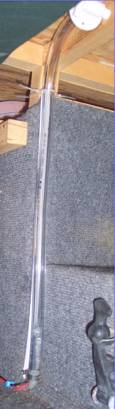
Tip:
Our digital tank gauges leave something to be desired. When only the bottom light (of 4) is lit, we might have as much as 1/3rd or 1/4th tank of fresh water, or we might have little or none left. If your fresh-water tank is visible, you can shine a light into it and see the water level. However, my tank is enclosed in walls, so I cannot see it. So, I decided to add a visual
gauge next to the tank. I bought a tee to go in the line from the bottom of the tank to the water pump, an elbow, a 2-foot length of clear hose, and a plastic valve, all for less than $10. I ran the hose up one edge of the tank enclosure, all the way to the ceiling of the storage area (that supports our bed). Thus, the hose fills with water to the same level as the tank when the valve is open. The valve must be closed to be sure no water goes into the storage area if I get the tank too full, and to be sure the pump does not suck the water out of the
gauge and then suck air rather than water. The valve must be open for a couple of seconds to allow the water level in the
gauge to equalize with that in the tank. A white blind behind the hose makes the water in the tube very visible.
Another view of the gauge can be seen on the left side of the last picture in Water
Pump Tip below
Frank
DeRemer
Return
to the Tip List.
Subject:
Water Pump Replacement 1
 Tip:
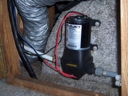
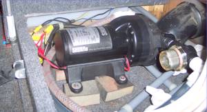
The old water pump was a Shurflo unit from June 1988. The pump would never turn
off unless you turned off switch above the stove in the kitchen area. Tip:
The old water pump was a Shurflo unit from June 1988. The pump would never turn
off unless you turned off switch above the stove in the kitchen area.
Changed
to a new Flojet automatic multi fixture pump model 4406-143 type IV. Purchased
from JC Whitney for a little over $80.
Now the pump only turns on upon
demand and shuts off immediately when the demand is turned off. 35psi and 3.2gpm
will give a good shower.
The
pump in a rear bath model fits under the closet. [On other models the pump
is under the bed next to the water tank.] The old pump had the motor
below the pump. Flojet says to place motor above the pump. To do this on the
Aero Cruiser the four bolts that hold the pump to the motor have to be pulled out
and the pump turned 180 degrees to get the flow going the correct direction.
Scale of 1 to 10 with 1 being easiest, this is a 2.
Happy trails
Rod Michaelson Note:
On my 1990 Rear Bath model the pumps is located under the bed next to the water
tank and darn hard to get to, so I cut a trap door in the bed platform -- with
appropriate bracing etc -- to get easy access to it and the pluming around
it. See "Water System, access under Shower, Bed & Pump"
for more information.
Keep on Cruisin', Tom Heald
Return
to the Tip List.
Subject:
Water Pump Replacement 2
 Tip:
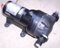
I found a used SHURflo SmartSensor water pump on eBay for a good price, so I decided to upgrade. This
pump has a microprocessor that senses the slightest reduction in pressure and runs the pump only as fast
as needed to keep the pressure up, rather than waiting until the pressure is below a threshold and hammering
away to get it back up. This pump also has five chambers instead of three; it pushes 5.7 GPM rather than
the 2.8
Tip:
I found a used SHURflo SmartSensor water pump on eBay for a good price, so I decided to upgrade. This
pump has a microprocessor that senses the slightest reduction in pressure and runs the pump only as fast
as needed to keep the pressure up, rather than waiting until the pressure is below a threshold and hammering
away to get it back up. This pump also has five chambers instead of three; it pushes 5.7 GPM rather than
the 2.8
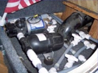 of the old pump. All that means a smoother, quieter delivery of more water just like home. Regular
price at Camping World is $233.33; I got a five-year-old for $33.00.
of the old pump. All that means a smoother, quieter delivery of more water just like home. Regular
price at Camping World is $233.33; I got a five-year-old for $33.00.
Pictured in the middle is the old pump as
installed by the prior owner of my rig. Note that my system had an
accumulator
 tank that smoothes out the operation of the pump: it flows longer
between pumps. Notice also that all the tubing is rigid. That transmits the
vibrations from the pump to everything around it. The installation instructions
say to use flexible hose for 18 inches on each side to reduce that effect. (That
improvement you can make for about $3 worth of hose.)
tank that smoothes out the operation of the pump: it flows longer
between pumps. Notice also that all the tubing is rigid. That transmits the
vibrations from the pump to everything around it. The installation instructions
say to use flexible hose for 18 inches on each side to reduce that effect. (That
improvement you can make for about $3 worth of hose.)
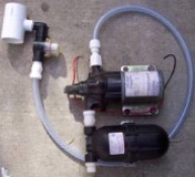
I made that improvement when I installed the new pump, as you can see next. Notice that I also
added a recommended strainer to prevent any debris that gets into the fresh water tank from
getting into the pump. I also added a
Fresh-Water Gauge which can be seen on the left side of the last picture and
is described in a separate tip. I plan to update this article with a report of how it works, after
I get some real experience with it.
Frank
DeRemer
Return
to the Tip List.
Subject: Recycling Grey Water
 Tip:
Having upgraded my fresh-water pump to a SmartSensor, I used the old water pump for an experiment, which,
if successful, will extend my dry-camping ability. I reasoned that it was a waste of fresh water to flush
it down the toilet. Why not use grey water instead? That would both make my fresh water last longer and
move some grey water into the black tank with each flush, thus making the grey tank last longer too. Furthermore,
if the grey tank gets full and
Tip:
Having upgraded my fresh-water pump to a SmartSensor, I used the old water pump for an experiment, which,
if successful, will extend my dry-camping ability. I reasoned that it was a waste of fresh water to flush
it down the toilet. Why not use grey water instead? That would both make my fresh water last longer and
move some grey water into the black tank with each flush, thus making the grey tank last longer too. Furthermore,
if the grey tank gets full and
 the black is not, which is usual for us, I could just do a continuous flush
for a while to move more grey water into the black tank. It sounds like a win-win-win (fresh, grey, black). But
will we like even a little grey water sitting in the toilet?
the black is not, which is usual for us, I could just do a continuous flush
for a while to move more grey water into the black tank. It sounds like a win-win-win (fresh, grey, black). But
will we like even a little grey water sitting in the toilet?
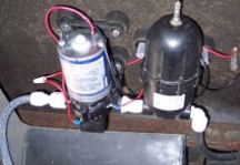
I bought (1) a tee to put in the drain line of the grey tank, before the dump valve, (2) a strainer to
 prevent any
debris in the grey tank from getting into the pump, (3) a flexible hose to go to the pump
and another (not shown above) to go to the toilet, and (4) the needed hose connectors. I mounted the
pump (and the accumulator tank) under the floor between the tanks. I ran a line to the toilet (difficult
to access), capped off the old supply line, and connected the toilet to the new line.
I cut out a 1-inch section of the grey dump line, removed the valve, glued in the tee, and replaced
 the dump valve. The picture
on the right shows that the strainer is accessible for cleaning and
replacement, just inside the small, contoured door above the dump valve.
Now, when I dump the tanks, I must clean the strainer and put a little fresh water in the grey tank
for the first flush or two say, one gallon. I also plan to add enzymes to eat the emoluents; with
every flush, they will be moved to the black tank where they are needed even more. After our first
shower, we will have plenty of grey water for flushes. We will also have to be careful not to put
coffee grounds and the like in the kitchen sink, but we have been doing that anyway. I hope, by fall
of 2010, to tell you how the system works.
Frank
DeRemer
Update: I have
now been on a seven-day trip by myself and a five-day trip with Lynda. I
am very happy with the gray-water-recycling set-up. I was surprised at how
much fresh water it saves and how low it keeps the gray tank. After seven
days I still had half a tank of fresh water, and the gray water tank never
showed more than one quarter full. With both of us for five days, we used
about 3/4 of the fresh and had about 1/2 gray at the end. I find the
toilet actually stays cleaner and is easier to swish out, as it always has
slightly soapy water in it -- a surprising side benefit. It was a
noticeable improvement over last year's experience during our 40-day trip.
Frank
DeRemer
Return
to the Tip List.

|
Copyright© 1999-2016
Freelance Ink.
All Rights Reserved.
|

|
| 